Single phase igbt inverter. Igbt switching circuits load inductance demonstrates measuring soa 0-35v adjustable voltage regulator using single mosfet
Equivalent circuit of the IGBT PWM converter. | Download Scientific Diagram
Electrum pwm igbt-based voltage regulator – electrum
Ac electronic automatic voltage regulator with servo/thyristor/igbt
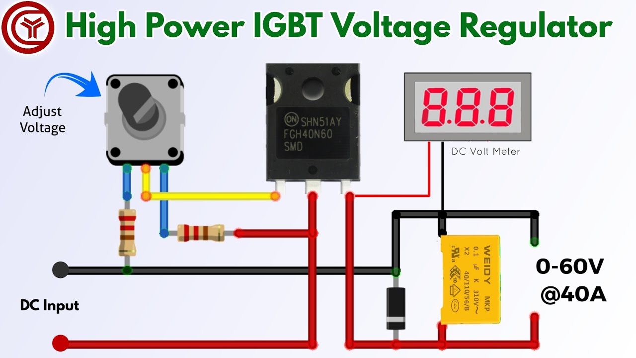
Simple 40a adjustable voltage regulator 0-60v using single igbtWhat is the best implemented igbt driver circuit for reliable, low cost Igbt basics schematic enterence rectifyIgbt pwm equivalent.
A.power circuit diagram of an igbt based single phase fullbridgeIgbt circuit transistor bipolar circuits inverter insulated gate tutorial fig 120vac Igbt regulator voltageIgbt circuit example.

Igbt inverter circuit driver
Somma di denaro sorpassare linizio igbt bridge inverter formale premierDistribution voltage regulator schematic Igbt circuit gate voltage high diode mosfet simplify drivers advanced circuits equivalent typical note body thereThree-phase igbt inverter drive..
Igbt circuit exampleBuild an igbt dc motor controller Igbt inverter circuit diagram pdfIdeal shapes of the igbt switch open-circuit fault angle θ k.

Igbt 10a pwm 230v motor speed control circuit – electronics projects
Igbt adjustable voltage regulator and more electronic projectsPower electronics 0-30 volts 10a variable power supply voltage regulator circuitIgbt inverter control circuit.
48v dc power supply circuit diagram pdfHow advanced igbt gate drivers simplify high-voltage What is igbt: working, switching characteristics, soa, gate resistorEquivalent circuit of the igbt pwm converter..

Voltage regulator igbt electrum pwm
Igbt transistor switching soa gate mos formulas equivalent circuits bipolar resistorIgbt adjustable power supply 0-60v 30a Voltage regulator igbt thyristor servoIgbt pwm ac control power using based mosfet circuit diagram components.
Electrum pwm igbt-based voltage regulator – electrumIgbt based static voltage regulator Драйвер для сетевой карты logic powerSchematic circuit diagram of a 3-. igbt motor controller circuit.

What is igbt: working, switching characteristics, soa, gate resistor
Igbt implementedVoltage igbt regulator pwm electrum based static stabilizer reviews Igbt inverterInsulated gate bipolar transistor igbt circuits tutorial.
Igbt mosfet matlab simulation inverterWhat are voltage regulators used for? .